
Signal Integrity Consultants
Donald Telian’s LIVE Gen2 SI Class
SiGuys Offers:
- Signal Integrity Training
- SI Coaching, on-call assistance
- High-Speed Serial Link Consulting:
- Simulation, Optimization, SI EQ Settings
- 1-64 Gbps and Beyond
- SI Design Reviews
SI GUYS IN THE NEWS
- Register for May/June 2026 LIVE Gen2 SI Classes
- Webinar: Simulate & Measure – Better Together
- SI Masterclass Videos: 3-min intro, 29-min detail
- Telian on Robert Feranec’s YouTube Channel
- Press Release: Telian to Teach SI in World Tour
- Bogatin’s Interview with Donald Telian
- SiGuys’ Articles at Signal Integrity Journal
- Telian podiums at Santa Cruz and Bass Lake Triathlons
Donald Telian’s book “Signal Integrity, In Practice” is available at Amazon (US, non-US). This is Gen2 SI.
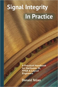
”…a narrative of what is left out in most textbooks. It is the stuff you would learn if you worked in a company with your desk next to a guru who has been doing this for forty years. This is the book that will accelerate your engineering judgment and possibly save you from multiple design spins.”
 Eric Bogatin, Professor, ECEE Univ of Colorado, Boulder (read Eric’s full book review)
Eric Bogatin, Professor, ECEE Univ of Colorado, Boulder (read Eric’s full book review)“…a perfect blend of intuition and theory. I was able to immediately apply the concepts to my design.”
Dan M., Hardware Engineer
Dan M., Hardware Engineer